

The pull-pull system for driving the rudder has been around as long as model
airplanes because it is simple, tough and keeps on working.
Text, photos and video by Tom Hintz
Posted – 5-26-2017
Pull-Pull cable systems have been around almost as long as model airplanes because they are super-strong yet light and provide precise control of the rudder. Using this cable system also allows moving the rudder servo forward in the plane where it is much closer to the CG. (center of gravity) That greatly increases the chance of balancing the plane with component placement rather than adding ballast weight.
There are a few pull-pull “designs” out there, primarily from low-buck Pacific Rim companies that demonstrate a rather frightening lack of concern for function or dependability. This kind of junk is meant to save the manufacturer money, not enhance your model.
In most cases, the pull-pull hardware included in mainstream manufacturer kits is more than sufficient in terms of strength and function if installed correctly. Granted some instruction manuals are little more than poorly-worded pamphlets that can be confusing to downright wrong. Fortunately, most pull-pull systems are installed the same way. Once you get installing a pull-pull system or two under your belt you can use the pull-pull part of the “instruction manual” for a coaster for your coffee cup.
The typical pull-pull hardware bag includes and length of braided steel cable, four threaded brass ends, four crimp tubes and four thread-on ball links or similar. The biggest variable is the type of clevis or ball link that gets screwed onto the threaded cable end pieces. I usually replace spring-metal clevises with ball links because I think they are more secure and add slop-free control.
The most frequent concern I get in FlyingRC.net email is that such a small diameter cable might not be strong enough. The reality is that the vast majority of cables supplied for this task exceed the needed strength by many times. If you dial in too much tension when setting up a cable pull-pull system those small-diameter cables can literally crush the hinges on the rudder. You are better off worrying about the quality of the ends that connect the pull-pull system to the control horns.
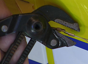
I use pliers like this because I can make
indented "stakes" across the brass
sleeve in two directions. Never had one
pull out.
Most often we have to build the pull-pull system in place because the cables run through openings too small for the ends to be in place. Also, one end of the pull-pull system can be much easier to work on than the other. Usually the ends at the rudder are easiest because they are outside of the fuselage where you can get tools on them. The length of cable supplied is generally quite a bit longer than needed and that helps make assembling this system easier.
The first step is of course laying out the pieces to be sure I have everything needed. Normally I double the cable and hold it up to the plane to be sure it is longer than needed and then cut it in half. However, in the QQ YAK 54 35CC ARF kit the cable comes in two properly sized pieces of high-end, coated cable.
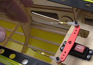
I usually install the rudder servo at this point, making sure that the output shaft is located as indicated in the instructions. Now, put the rudder servo arm (sized per the instructions) on the output shaft making sure that it is square to the fuselage. This arm will have to come off a few times before we set it in place permanently so I leave its center screw out for now.
This is a good time to bind the radio gear to the transmitter so we can make sure that the rudder servo is centered. Usually it takes some adjusting of the sub trim to get the servo arm perfectly square to the fuselage but we need to do that before making up the cables. Having the radio gear functioning allows us to use the centering power of the servo to resist accidental pulling of the cables while adjusting them and finishing the installation.
When assembling the ball link ends to the threaded end pieces I have found it helpful to make a mark at roughly half of the available thread. Then we can screw on the ball link to that mark and know that we have a good amount of adjustment at each end of the cables for tweaking them as needed in the future.
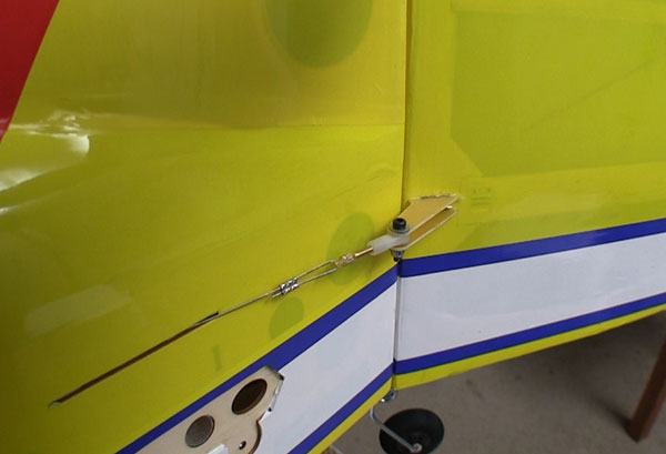
Because it is so much easier to access the cable at the rudder I go ahead and make up the ends at the servo and hook them up. Then the excess cable is at the rudder where I can snug up the cable. Make sure the cables are both as slack-free as we can get at this point and then crimp the tubing to lock them in place. Cut off any excess cable. It is common for the cable to be a little loose after we finalize the length and we will dial that out using the thread-on cable ends.
You can literally crush the rudder hinges
if you get carried away with cable
tension.
The instructions frequently call for using a “crimping tool” when squeezing the crush tubing down to lock in the cable length. Since few of us have a purpose-designed crimping tool I use a large pliers that has coarsely serrated jaws. When crimping the tube onto the cables I turn the jaws of the pliers so the serrations are diagonal to the length of the tubing. Then I can turn the pliers once more to add a second impression of those serrations crossing the first ones to ensure that the cable will not slip during operation.
The last step is to take the remaining slack out of the cables. The idea is to shorten each cable using the screw-on ball links until the cable is not sagging excessively. There is no real tension on the cable, it just does not flop around.
It certainly is possible to adjust in tension so that the cables are drawn tight like the strings of a guitar but that is way too much tension for our purposes here. That much tension will crush the rudder hinges and can work the control horns out of the rudder. There is nothing good to be gained by tightening the cables up too much. Shorten them until the sag is almost totally gone and leave them alone!
We want to spread the adjustments across both ends of the cable. I disconnect one end from either the servo or rudder and then take the same number of turns on both cable ends. There is only so much adjustment room on these cable ends so we want to balance the number of turns on both ends.
It is not uncommon for the cables to loosen up a bit after the first several flights. I think most of this comes from loops at the ends stretching out to their final shape. Check your cables often and adjust them as needed but don’t get carried away with tightening them up. Other than that, pull-pull systems are very trouble-free but offer superior performance and weigh savings.
See the QQ YAK 54 35CC ARF build page – Click Here
Have a comment on this story? –Email Me!