

Getting your new gas engine properly mounted on your new plane is easy, once
you have done it a few times.
Text, photos and video by Tom Hintz
Posted – 6-9-2017
One of the most important parts of assembling an ARF (almost ready to fly) plane is installing the engine. This is the single heaviest component and it literally hangs out the front on “stilts” in the form of standoffs. Moving the engine in or out in surprisingly small increments can have a huge impact on the final balance of the plane. Adding extra weight to a plane to balance it is always a last resort. The planes’ manufacturer provides a specific dimension for prop washer to firewall distance and it is our job to hit that as perfectly as possible. The final engine position is critical for other installations such as cutting the cowl, making throttle and choke linkage and fuel lines.
Most firewalls arrive without holes for the engine mounting bolts, mainly because of the large number of possible engines that can be used. Some kits provide templates that represent the major engine brands. Others might include a type of sticker with locating cross-hairs and holes printed on it. These templates can be good news for lots of other engine brands as many use the same mounting bolt pattern as the more established models so you need to check your engine against the included templates.
You should also check every page of the instruction manual that came with the engine and on the engine manufacturers website as they often provide a printable template that you can use to lay out the mounting holes correctly.
Another relatively modern enhancement is the inclusion of a laser (or similar) etched cross-hair on the firewall that lets you align templates precisely to get the engine centerline where it is needed for that airframe. You might have to extend the cross-hair markings on the template but that is easily done with a straight edge and a bit of care aligning the original marks. All this is worth the effort because the engine needs to be placed correctly on that firewall so that with the built-in thrust angles, the prop washer at the front of the engine aligns with center of the cowl.
Many firewalls are marked with the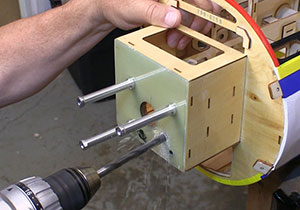
mounting hole for popular engines. You
can also find templates for your engines
bolt pattern.
The only real caution regarding drilling the firewall is to be sure the holes fit the bolts but not loosely. Gas engines produce lots of vibration that can loosen fasteners or turn the engine on the firewall if there is excess play between the holes and mounting bolts that pass through them.
While you are drilling things, this would be a good time to decide if you need a center hole at the junction of the cross-hairs that aligns with the carburetor inlet. We used to see how close the end of the carb came to the firewall and if it was less than ½-inch or so we drilled the center hole to let the carb breathe better, particularly at speed. Today, I always drill the center hole, usually 1-7/8” diameter (a “looks big enough” calculation.) if the airframe does not come with one just to be sure.
Because the airframe manufacturer has no idea what engine you will be using or what the dimensions of that engine might be they give us a prop washer to firewall measurement with which we can calculate the needed stand-off length. I lucked out in that I bought a complete QQ YAK 54 35CC ARF package from Flex Innovations that included the DA35 engine which came with the correct length standoffs. In most cases we will have to do some measuring to determine the standoff length. The good news is that if I with my math phobia can do this you had better be able to or you might have significant issues.
First, we need to find the prop washer to firewall dimension in the instruction manual. Next, lay your engine on the bench and measure from the face of the prop washer to the back, machined surface of the engines mounting flange. Subtract this measurement from the listed prop washer to firewall distance to get the length of the needed stand offs. See the video below for a demonstration showing how to do this.
If you have a combination square that has a mm scale (most manuals use metric dimensions) this is even easier. Extend the blade of the square to the prop washer to firewall dimension and lock it in place. Hold the flat surface of the square on the prop washer with the blade extended towards the rear of the engine. All you do is read the scale at the edge of the mounting flange of the engine to see how long the stand offs need to be. Again, see the video below as showing this is way easier than explaining it!
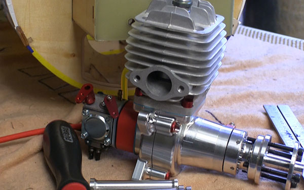
Standoffs are used to get the proper
firewall to prop washer distance for
your plane. Get this right!
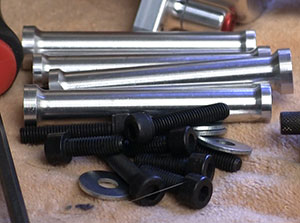
It is important to remember that the firewall of most airframes is made from wood that can crush to some degree under the pressure of tightened bolts. It is crucial to use washers to expand the footprint of the standoffs and bolt heads to minimize the crushing of the wood.
Some standoffs have a large end and a smaller-diameter end. In this case, the larger end goes against the wood. If the standoff set did not come with large-diameter washers go buy some before permanently installing the bolts inside of the engine box. I like to use washers with an outside diameter around 1” and an inside diameter that closely fits the bolt shank. Many home centers and hardware stores have washers like this, usually called “fender washers” as they are like what used to hold fenders on automobiles.
Though I have tried many different sequences, mounting the engine is a repetitive task when building a plane. The first time the engine is mounted I draw out where the throttle pushrod will go through the firewall. This linkage will be made later but the path it takes should be obvious by now if we know where the throttle servo is positioned. If not already done this is a good time to find a logical home for the throttle servo that simplifies its linkage as best we can.
This is also a good time to install the muffler on the engine to be sure there are no conflicts with structure or other components. With the muffler in place I can better plan the route of the fuel line to be sure it stays away from the hot surfaces and other components within the cowl. I mark where the fuel line will come through the firewall so I can drill that hole at the same time I drill the throttle linkage hole, both after removing the engine.
I always wrap fuel lines with plastic spiral protector that is commonly used on electrical wires. This protection increases the size of the hole needed for the fuel line but goes a long way towards preventing chaffing where the fuel tubing encounters edges that can cause a problem that typically develops later in response to vibrations of the line during flight. I keep a length of fuel tubing in the shop with the plastic spiral protector on it so I can check that the fuel line will come out of the firewall to the fuel inlet on the carb without kinking or other issues.
With the holes for “through firewall” components marked I remove the engine and drill those holes. I use brad point woodworking drill bits as they tend to blow out the back side of the firewall less than other bit types. After drilling and cleaning up the edges of the new holes if needed I soak the sides of the holes with thin CA to protect the laminations of the plywood from gas and oil. I am not bashful when applying the CA as this fuel protection is important. I also turn the fuselage 90-degrees and re apply the CA to be sure I get the entire surface within the holes protected.
I never know how many times I will install and remove an engine during the build process. I go through this cycle as many times as I feel necessary to get everything installed as straight and accurately as possible. Having the engine on or off makes many of these operations easier or more accurate. Both are important throughout the building of an airframe.
An important point is that I do not use thread locker during these trial fits. However, when installing the engine for the final time, all fasteners get Blue Loctite – no exceptions. The engine is the heart of the vibrations and securing it and everything else as best we can is only common sense.
All that remains to be done with the engine is getting it fired up, set the carb some if need be, set the end points of the throttle servo and take it flying. If we did everything else properly during the installation of the engine the plane and its engine should perform just fine. Taking the time to install the engine right can head off a bunch of frustrating problems down the road. I’d rather invest some time during the build to get more flying time when it’s done.
Have a comment on this How-To? –Email Me!