

Having to install a gas engine on beam mounts nearly went extinct but with smaller
gas engines and planes, the beam mounts are back.
Text, photos and video by Tom Hintz
Posted – 2-7-2018
I have enjoyed most things about flying RC planes over the last 30-some years including building the modern ARF (Almost Ready to Fly) kits. However, I have been consistently disenchanted with beam-style engine mounts that whole time. I was disappointed to see these horrid pieces were chosen for inclusion in the Hangar 9 10cc Valiant kit. The dichotomy between the best airframe design in decades and a woefully poor excuse for engine mounting is frustrating on a good day, and unexpected from Hangar 9.
I understand the reasoning for creating a smaller gas version of the venerable Valiant. However, the kit design suffered a major glitch when it came to the choice of mount for the 10cc-class engine. Because these small gas engines frequently still use mounting flanges cast into the crankcase they introduce a huge opportunity for compromising needed engine thrust angles. I think this demonstrates the need for a better mounting concept for these smaller engines. The mounts themselves work fine but the RC flying community is quickly losing participants that have dealt with or fully understand engine thrust angles and there-in lies a big problem.
Modern ARF planes use super-accurate, laser-cut parts assembled on equally precise jigs to produce straight and true planes. Those manufacturing processes insure that the engine thrust angles, usually slightly right and a little down (can be different on individual planes) are built into the fuselage and its firewall. Thrust angles are critical to how a plane flies so angling the firewall to point the engine at the correct angles is another way to get a good-handling plane in the hands of the modeler.
With the rear engine mounts found on larger gas engines we simply mount the engine directly to the firewall using four equal-length mounts or standoffs. Simple and effective. No muss, no fuss - the engine is automatically square to the firewall, so the thrust angles are correct.
We must remember that we have entire generations of RC pilots that have never built a kit (stick-built so to speak) that required them to check and/or set the thrust angles prescribed in the instructions. These newer modelers have not had the opportunity to learn about engine thrust angles or their importance.
People are trying to build in right thrust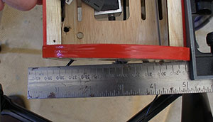
by setting the engine crooked on the beam
mounts. The firewalls in today's planes
usually have that offset built in.
What got me thinking about all this were the beam-style engine mounts and the instructions that came with the Hangar 9 10cc Valiant. Using the beam style mounts forces the modeler to drill the mounting holes for their engine and that opens the door for a major, plane-endangering mistake. The instruction manual which in all other regards is very well done, mentions engine thrust angles but specifies nothing. The following is the passage in the Hangar 9 10cc Valiant instruction manual referring to thrust angles, exactly as it appears in the manual. “The engine mounts will angle to the right and slightly down when viewed from the top and side of the fuselage. This is to compensate for the thrust of the engine.” That’s it, nothing on how the engine must be square to the beam mounts and firewall or those critical engine thrust angles can be dangerously compromised.
I have been a big fan of Hangar 9 models and their Valiant line in particular. However, they need to fix this thrust angle “black hole” that could make the model very difficult to fly for an inexperienced pilot. Also, I would encourage experienced pilots being asked to do maiden flights on the Hangar 9 10cc Valiant to look closely at the thrust angles and ask questions before putting this or any new plane, into the air for the first time.
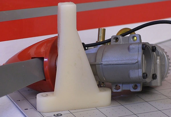
When I began fitting the NGH GT09 Pro 9cc Gas Engine to the beam mounts it was obvious that they were longer than needed. The ends of the beams missed the prop and spinner but were too close to things like the magnetic pickup that triggers the ignition. To error on the side of caution I did a quick test fit that showed me where I could safely cut off excess beam length.
With the beam mounts loosely bolted to the firewall I set the NGH GT09 Pro 9cc Gas Engine on the beam mounts and carefully set the engine square to the firewall. Next, we need to set the prop washer to firewall distance. This is a critical dimension for achieving the correct CG (center of gravity) without adding excess weight and getting the cowl to fit properly. See Resources below for more on fitting a cowl.
When satisfied with the engine position on the beam mounts I carefully locate and mark the location for one bolt. I take the time to remove the mount for drilling on my drill press, in a drilling vice to be sure the hole is as close to perfectly square as possible. Then I use that hole to attach the engine to the beam mounts that have been again bolted to the firewall with the bolts snugged down this time.
Using a drill press entails some setup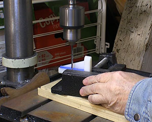
but is worth the effort in straight holes.
Before continuing I check as closely as I can to be sure the engine itself is square to the firewall. Once satisfied I tighten down the one bolt to keep the engine still. I can then use a long drill bit that allows reaching the holes in the engine mounting flange more squarely by missing parts of the engine that would contact the larger-diameter chuck. I can then make divots in the beams for the remaining bolt holes. I do not drill the holes through the beam mounts at this point but rather pull the mounts from the plane. Back at the drill press I put the beam mounts in the drill vice and using the divots, drill the remaining holes and keep them very square to the beam.
I know this procedure takes a little longer than just holding the engine on the beams and marking the bolt holes as close as can be done that way with a pencil or marker. Even with masking tape on the beam it can be difficult to mark the holes precisely without moving the engine. Since I started using the one-bolt-first process most of the engine mounting bolts can be installed and the nuts and washers assembled finger tight without having to turn them in with a driver. That means way less stress is built into a mount when completed and tightened down fully. Remember that this is still a largely wooden airframe and “stored” energy like built in tension of the engine mount bolts can slowly induce a distortion that could impact how the plane flies later.
While most kits come with fasteners meant to secure the engine and mount I replace them with known high-quality fasteners I keep in my shop. Nearly all those fasteners come from RTL Fasteners, my “go to” source for that kind of hardware. (Link in Resources below) High-end fasteners are just way too cheap to not use them “just to be sure”.
For mounting engines to a wooden firewall, I use blind nuts whenever I can. After mounting the fuel tank and other equipment inside the fuselage getting at nuts on the inside end of the engine mounting bolts can be difficult. I put the blind nuts in as part of my normal assembly and my life later is way better if I need to slip a washer or spacer under an engine mount.
I also use flat washers under bolt heads and nuts. In addition to spreading the clamping forces over a larger area, flat washers help prevent the bolt head or even insert locking nuts from getting a bite on the surface they are pressed into. That indentation can act much like a wrench and hold the nut while the bolt vibrates back and forth even a tiny amount. That is how otherwise tight fasteners inexplicably loosen up. Here again, my peace of mind is well worth the cost of a bag of washers.
At this point I install the engine and mount to the firewall and snug the bolts down just enough to prevent the engine from flopping around. I make one final check to be sure the engine is square to the firewall before tightening all the bolts. Make one final check to be sure nothing moved and let the assembly sit overnight.
Because wood and many composite materials can compress somewhat I go back over all the fasteners the next day and then repeat that check occasionally when I remove the cowl for other maintenance. We have considerable amounts of vibration in our planes which should make tightening nuts and bolts a regular task, especially when we uncover seldom seen fasteners like engine mounting hardware that lives inside a cowl. It only takes a few minutes to go over a bunch of fasteners but could easily prevent a failure that could total a plane out.
Installing a Gas Engine – Click Here
My Cowl Cutting “System” – Click Here
Visit RTL Fasteners – Click Here
Have a comment on this story? Email Me!