

Everybody has their way of doing things but many of the setup tasks in a new plane
are common to most types of RC planes.
Text, photos and video by Tom Hintz
Posted– 5-14-2015
This How-To was suggested by some visitors to my site to help them with building my Aeroworks 50cc Edge 540 ARF. It just seemed like a good idea all around so I did this one and will likely do some on other planes in the future. The techniques I use to mount everything is the best I can come up with but there are certainly other good methods and you have to determine which is best for your situation.
You can assume that my using something in my planes is an endorsement because I simply will not fly cheap stuff just to save a buck. My bucks are way too hard to come by to squander them stupidly. I have faith in everything I put in my planes or they do not leave the ground.
My Aeroworks 50cc Edge 540 ARF is powered by a DLE 61cc engine equipped with a compact Pitts-style muffler. The engine is mounted on 2.68” stand offs with one ¼” spacer under each leg. That gives me a firewall to prop washer dimension of just under 7” and that allows plenty of clearance between the 3” spinner back plate and the front of the cowl.
The throttle linkage is 4-40 rod threaded on one end and a soldered threaded end on the other with 4-40-ball links on both ends to eliminate any play that could make setting a reliable idle way harder. The choke is manual using a simple rod I made in a few minutes with Z-bend pliers. It’s cheap, trouble free and easy to use.
The DLE ignition module is mounted on the side (outside) of the engine box as most do with the ignition battery inside the motor box on the floor about halfway through the bulkhead.
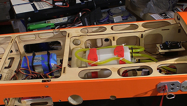
I use RotoFlow tanks almost exclusively and put a 16oz tank in the Aeroworks 50cc Edge 540 ARF. I am planning on going to a 20oz RotoFlow soon to get closer to 10 minute flights without running the tank down too far. The fuel tank is placed at the wing tube to keep this major varying weight as close to the CG as possible so that burning off fuel has little impact on how the plane flies. I put a Sullivan Crap Trap in the line going to the carb as a final stop for junk coming from refueling or the tank.
Even with giant scale planes, demands
for space in the fuse can be tough to
figure out.
I used HiTec HS-7954SH high voltage digital dual bearing servo (403oz. at 7.4V) on each aileron, both elevator halves and the rudder. All of the control servos use Hangar-9 aluminum arms that are tough, have a center bolt in place of the Phillips type screw plus they have two pinch bolts that lock them to the servo output shaft and eliminate slipping or coming loose. I use 1.5” arms on the ailerons and elevators and a 4” double rudder arm. I went to the 4” arm so that the pull-pull ends at the servo are the same width as the connections at the rudder. If these widths differ one cable will go slack whenever you deflect the rudder.
I use a HiTec HS-430BH, high voltage digital servo (69oz at 7.4V) on throttle with 50% current reduction programmed in should it stall. I used one of the blue aluminum arms HiTec supplies with their bigger servos and re tapped the hole for the 4-40 bolts that secure the ball links.
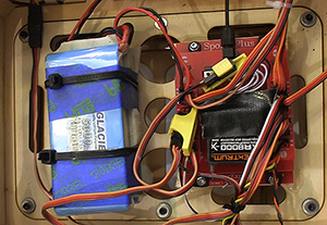
Two 7.4V LiPos, (5000mAh each) power the receiver and servos. A single 7.4 LiPo, 2800mAh pack powers the ignition. I won’t fly a giant scale plane without redundant batteries and the weight penalty to carry two 5000mAh packs over the 2700mAh or so packs often recommended is minimal. To me having the capacity to fly all day without flirting with running out of battery power is well worth the tiny bit of performance this luxury might cost.
The RX packs were placed next to the Smart-Fly PowerExpander Sport Plus in the bay behind the wing tube and this proved to be perfect for getting the CG correct as indicated by the CG Buddy Aeroworks includes with the plane.
I should note that there is a removable floor at this part of the fuselage, held in place by six screws. On one of the first flights I could hear a heavy buzz-type rattle when the plane idled. When I removed the canopy I found that all but two of the screws (both on the front edge) had fallen out of that floor and it was vibrating heavily, my Spektrum AR8000 receiver and all. I replaced those screws and added thread locker and rubber-backed washers to keep this floor in place. So far that has worked well but I check it before each day at the field.
The Smart-Fly PowerExpander Sport Plus is mounted to a pair of 3/” square spruce rails that are epoxied to the floor with two screws in each rail (under the mounting lip of the Smart-Fly PowerExpander Sport Plus) for security. I put a piece of foam under the Smart-Fly PowerExpander Sport Plus to dampen vibrations that may try to flex it, just in case.
This Smart-Fly PowerExpander Sport Plus has a fiber optic cable that connects it to the ignition cut off near the front of the plane. This allows me to shut the motor down from the radio but there is no electrical connection between the ignition and the receiver. There is a small board up front that acts like a switch to turn off power to the DLE ignition module when the main Smart-Fly PowerExpander Sport Plus board sends a beam of light down the fiber optic cable. This sounds way more complicated than it is. But it is very effective and very light.
Making certain there is no conflict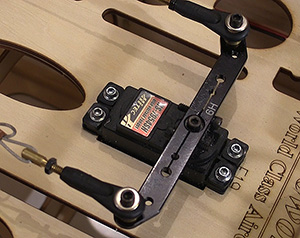
between moving servo arms can
easily save a plane.
Because there is very little room above the wings before the canopy, I had to install both access panels near the cowl. The main panel has a pin and flag that when removed turns the entire system on. If this switch were to fail in flight, it is made to fail to the ON position. Inserting the pin breaks the connection to “turn the system off.” The ignition access panel has a light that indicates the ignition is active, a charge jack for the ignition battery and a fuel dot that takes the place of something we would have to install anyway.
I use thread lock on virtually everything but the wood screws holding the servos in. I use thread lock on the servo arm bolts, the ball link bolts, all engine mounts, prop bolts, spinner bolt, landing gear bolts and even the bolts holding the cowl on. Thread lock is cheap; stuff falling apart in flight can get very expensive very quickly.
That’s about it. I try to not get fancy with my systems or their installation. I want solid and dependable before glamour. I like parts that eliminate play, hold adjustments and don’t flex. Some of these pieces do cost more but that actual increase in money is tiny compared to saving that amount and losing a plane.
The actual layout varies somewhat between planes to achieve the correct CG without adding excess weight but I use the same parts and pieces on most of my giant scale planes. If I put a gas engine on it, it will have most of these pieces.
I want the security but to best combat the advance of Alzheimer’s I need to be able to focus on flying so I get the best mental workout that I can. Flying the planes, learning new things in the air and then producing this content and bringing it to you has proven to be a huge help in my fight to slow the progression of Alzheimer’s. Replacing a killed plane won’t help anything.
Have a comment on this story? –Email Me!